September 1999
Split Mode Is Critical For Upgrading Fault Tolerant Systems
BY JEFF HIRSCHL
In most features, we avoid running vendor-specific material. However, for articles
directed at the Internet telephony developer community, a less generic and more
nuts-and-bolts approach seems appropriate. Of course, such an approach is by its very
nature more vendor-specific. To help readers distinguish between ordinary features and
development-oriented features, we run the latter under the heading Developer’s
Corner.
Using split mode, an operator can reduce planned fault tolerant application downtime
resulting from an operating system, application, or CPU module upgrade to as little as a
few seconds for a typical system configuration. The split-mode process also preserves the
old operating environment while the new, upgraded environment is thoroughly tested. Either
the old or new environments can provide application service, and the old environment is
available until the service provider decides to commit the new environment to fault
tolerant operation.
FX SERIES ARCHITECTURE OVERVIEW
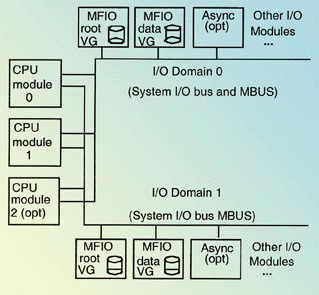
Motorola’s FX Series fault tolerant architecture, features a redundant set
of CPU and input/output (I/O) modules residing on two separate I/O domains. As shown, CPU
modules have access to both I/O domains. Each I/O domain includes a system I/O bus, used
to pass data, and a maintenance bus (MBUS), used to control system modules. Via the MBUS,
the system can power any module on and off, making it easy to shut down and effectively
isolate a module from the rest of the configuration. The following I/O module types are
currently available:
- Multi-function I/O (MFIO) Module — Ethernet and SCSI with on-board disks and/or
removable media drives.
- Asynchronous Communications Module — 16 ports.
- Other I/O Modules — Motorola I/O modules are available for Ethernet, SS7, T1/E1,
and X.25 protocols.
I/O modules are normally configured on separate I/O domains as redundant pairs. In most
cases, multiple pairs of each module type can be configured. To provide data redundancy,
the disks within an MFIO module are generally mirrored to the corresponding MFIO module in
the opposite I/O domain.
Figure 1 shows two sets of redundant MFIO modules,
an optional Async board, and a notation that other modules could be configured. One pair
of MFIO modules contains the system’s mirrored root volume group (VG), used generally
for system support files, while the other pair contains a mirrored data volume group,
which contains application data.
An FX Series system contains either two or three CPU modules, each of which contains a
CPU and local memory. Each CPU module executes code from its own local memory in lockstep
with the other CPU modules. Only one module, the master, makes I/O bus accesses. The
remaining CPU modules, known as checkers, must agree with the master on all addresses and
data passed on either system I/O bus. Any disagreement causes a dynamic reevaluation of
the system configuration, which may include shutdown of a bad module or change of
mastership.
At any time, a CPU module or I/O module can fail or be hot-pulled, and the system will
automatically switch operation to a redundant module. If a failed module happens to be the
master CPU module, a new master CPU module is chosen.
SPLIT MODE USES
Split mode eliminates hours of planned downtime for the following upgrades:
- Operating system software updates or upgrades.
- Application software upgrades.
- CPU module upgrades.
- CPU module firmware upgrades.
Split mode is not used for operations that can be done in normal fault tolerant mode on
the FX Series, such as:
- Routine replacement of any module with another of the same type and revision.
- Upgrading of I/O modules.
- Adding or removing I/O modules.
- Adding or removing CPU modules of the same type and revision.
HOW SPLIT MODE WORKS
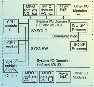
Split mode splits the normally fault tolerant FX Series system into a pair of
non-fault tolerant systems. A CPU module is logically paired with one I/O domain to form
SYSOLD, and SYSOLD continues to provide application service. Another CPU module is paired
with the other I/O domain to form SYSNEW, the system which is first upgraded. A third CPU
module, if present, is not used in split mode. The diagram in Figure 2 shows SYSOLD as CPU module 0 paired with I/O domain 0 and SYSNEW as CPU
module 1 paired with I/O domain 1, although either system could be created from any
combination of CPU modules and I/O domains.
Once the CPU modules enter split mode, they take on a relationship of primary and
secondary instead of master and checker. The primary CPU module provides I/O bus
arbitration and normally services active applications. To provide communication between
SYSOLD and SYSNEW, an inter-system communication service provider (ISC SP) runs on each
system. The ISC SPs in the two systems communicate via a dual-ported RAM provided in each
CPU module.
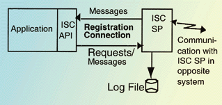
The ISC SP allows transfer of files between systems, execution of programs on the
opposite system, and exchange of messages among programs which are registered with the ISC
SP. An application program interface (API) is provided to allow applications to register
with and communicate with the ISC SP. All ISC SP transactions are logged, which assists in
any needed fault diagnosis. Figure 3 shows the
structure of the ISC SP facility.
Before the split-mode process begins, an ISC SP is started on the one fault tolerant
system that exists at that time. Upon startup, the ISC SP notifies user-defined
applications via signal that the ISC SP is available to accept registrations. Applications
which participate in split mode then register with the ISC SP via the API. After the
system is split, the opposite-system ISC SP is started in a similar way.
SPLIT MODE FLEXIBILITY
The split mode process takes SYSOLD and SYSNEW through a series of states, under
software control as shown in the Table. State transitions are requested via a
Motorola-provided utility and generally proceed automatically. During transition through
the states from SPLIT to SWITCHED state, primary operation is transferred from SYSOLD to
SYSNEW, a process known as “switchover.” After switchover, application service
is done by SYSNEW.
The split mode process normally proceeds linearly through the states from FT_START to
FT_COMPLETED. However, with a few exceptions, split mode can traverse states forward (in
the direction towards FT_COMPLETED) or backward (towards FT_START) at will. For example, a
forward transition from FT_START to SPLIT could be followed by a backward transition to
SIMPLEX state. Or, the operation could be switched over to SYSNEW by transitioning to
RESUMEDVGAPPS_SYSNEW. Then, the operation could transition back to SPLIT and then
switchover back to SYSOLD, thereby transferring operations back to the original SYSOLD
system. There are a few restrictions on transitions:
- SYSNEW must be booted before making a transition forward from SPLIT state. Otherwise,
there would be no system with which to perform switchover.
- Once RESUMEDVGAPPS_SYSNEW state is reached, any backward transition moves the system all
the way back to FT_START state. This behavior provides a convenient method to recover
fully to SYSOLD should the need arise.
- Once a transition to UNSPLIT state is made, a commitment has been made to reintegrate
the SYSNEW system. No backward transition is possible from that point.
State transition errors cause the system to revert to the immediately-previous state.
Thus an error occurring during transition from SIMPLEX to SPLIT state, for example, would
cause the system to revert to SIMPLEX state.
APPLICATION PARTICIPATION
Several approaches are available to allow applications to participate in the
split-mode process:
- Applications can register with the ISC SP, receive notifications of split-mode events,
and manage themselves automatically through the split-mode process. This approach requires
application changes to add registration and split-mode handling. Applications
knowledgeable about the split-mode process are known as “split-mode-aware”
applications.
- One application can be made split-mode-aware and manage other applications through split
mode. For example, when the split-mode-aware application receives a message to suspend, it
might pass this message to an application, which is not split-mode-aware, for action.
- Finally, no applications need be made split-mode-aware. No user application changes are
needed to use this approach, but operations must manually transition through the
split-mode process. For example, the operator must manually suspend applications before
asking the split-state utility to start the switchover process.
We’ve looked at the workings and flexibility of the FX Series split-mode process.
Without split mode, CPU module, operating system, and critical application software
upgrades normally require a long application service downtime. Using split mode on the
fault tolerant FX Series, a system upgrade can be done with a very small interruption of
application service. Moreover, split mode allows an operation to verify the upgraded
system before system operations are committed.
Jeff Hirschl is a principal staff engineer for the Motorola Computer Group. The
Motorola Computer Group (MCG) is part of Motorola’s Integrated Electronic Systems
Sector (IESS). MCG offers standard, semi-custom, and full custom products, and has
extensive experience ranging from high volume, low cost embedded computer boards to fully
fault tolerant systems for mission critical applications. MCG combines its advanced design
engineering capability with responsive, world-class manufacturing operations and a
comprehensive knowledge of customers’ unique business needs in the markets it serves.
Detailed information is available on the MCG Web site at www.mcg.mot.com.
Figure 1
Motorola's FX series fault tolerant architecture
[return to text]

Figure 2
FX series system split into a pair of
non-fault tolerant systems
[return to text]

Figure 3
The ISC IP facility structure
[return to text]
 |